VTK provides some convenient algorithms to help us display the whole digital elevation model (DEM). My university major is Geometry Information Science, it’s so exciting for me to write an article about DEM since I became a professional software develop programmer.
In the following section, I will show how to do it and put control points and the interpolator line between them on the surface of the model.
Read DEM file and extract geometry of model, there will be nothing in renderer window if we don’t extract geometry.
  const char* fname = "/Users/weiyang/Downloads/VTKData/Data/SainteHelens.dem";
  vtkSmartPointer<vtkDEMReader> demReader = vtkSmartPointer<vtkDEMReader>::New();
  demReader->SetFileName(fname);

  // Extract geometry
  vtkSmartPointer<vtkImageDataGeometryFilter> surface = vtkSmartPointer<vtkImageDataGeometryFilter>::New();
  surface->SetInputConnection(demReader->GetOutputPort());

  // Define a LUT mapping for the height field
  double lo = demReader->GetOutput()->GetScalarRange()[0];
  double hi = demReader->GetOutput()->GetScalarRange()[1];

  vtkSmartPointer<vtkLookupTable> lut =
    vtkSmartPointer<vtkLookupTable>::New();
  lut->SetHueRange(0.6, 0);
  lut->SetSaturationRange(1.0, 0);
  lut->SetValueRange(0.5, 1.0);

  vtkSmartPointer<vtkPolyDataMapper> demMapper = vtkSmartPointer<vtkPolyDataMapper>::New();
  demMapper->SetInputConnection(surface->GetOutputPort());
  demMapper->SetScalarRange(lo, hi);
  demMapper->SetLookupTable(lut);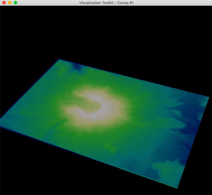
Use vtkWarpScalar to move points along points’ normal by the scalar amount times the scale factor, then we can see the terrain’s height.
  vtkSmartPointer<vtkWarpScalar> warp = vtkSmartPointer<vtkWarpScalar>::New();
  warp->SetInputConnection(surface->GetOutputPort());
  warp->SetScaleFactor(1);
  warp->UseNormalOn();
  warp->SetNormal(0, 0, 1);
  warp->Update();

  // ...
  demMapper->SetInputConnection(warp->GetOutputPort());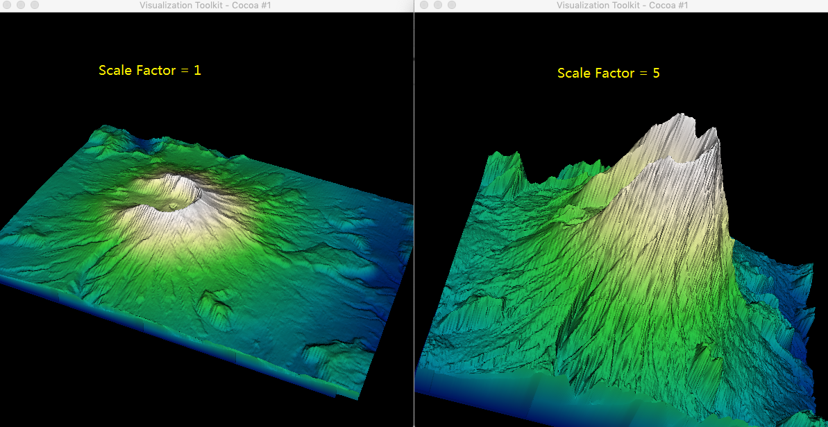
To smooth the surface of the model, we can use vtkPolyDataNormals to turn off the splitting of sharp edges.
  vtkSmartPointer<vtkPolyDataNormals> normals =
    vtkSmartPointer<vtkPolyDataNormals>::New();
  normals->SetInputConnection(warp->GetOutputPort());
  normals->SetFeatureAngle(60); // define sharp edges.
  normals->SplittingOff(); //Turn off the splitting of sharp edges.
  normals->Update();
  // ...
  demMapper->SetInputConnection(normals->GetOutputPort());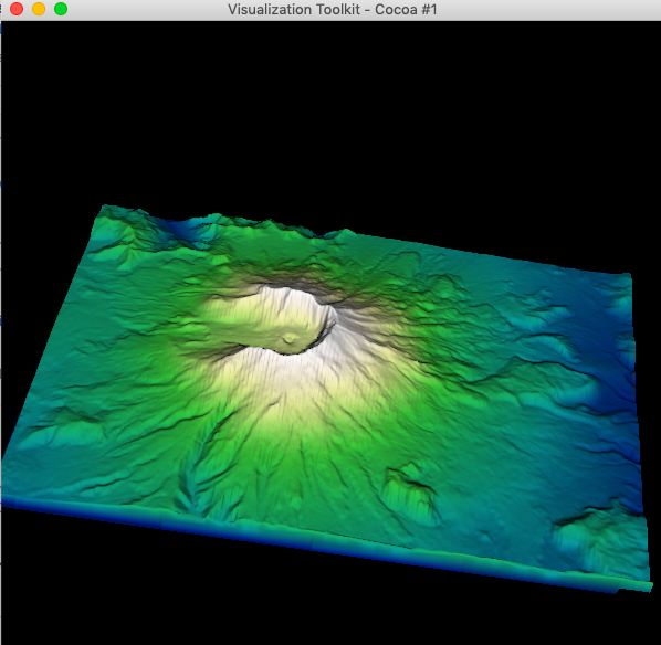
Now we can put control points on the surface of DEM, it’s time for vtkTerrainDataPointPlacer and vtkTerrainContourLineInterpolator to stand on the center area of the stage. They help us to move line and points on the terrain.
  vtkSmartPointer<vtkContourWidget> contourWidget =
    vtkSmartPointer<vtkContourWidget>::New();
  vtkOrientedGlyphContourRepresentation *rep =
      vtkOrientedGlyphContourRepresentation::SafeDownCast(contourWidget->GetRepresentation());
  rep->GetLinesProperty()->SetColor(1.0, 0.0, 0.0);
  contourWidget->SetInteractor(iren);

  vtkSmartPointer<vtkTerrainDataPointPlacer> pointPlacer =
    vtkSmartPointer<vtkTerrainDataPointPlacer>::New();
  pointPlacer->AddProp(demActor); // the actor(s) containing the terrain.
  rep->SetPointPlacer(pointPlacer);

  // Set a terrain interpolator to make points lie on the terrain.
  vtkSmartPointer<vtkTerrainContourLineInterpolator> interpolator
          = vtkSmartPointer<vtkTerrainContourLineInterpolator>::New();
  rep->SetLineInterpolator(interpolator);
  interpolator->SetImageData(demReader->GetOutput());

  interpolator->GetProjector()->SetProjectionModeToHug();
  contourWidget->EnabledOn();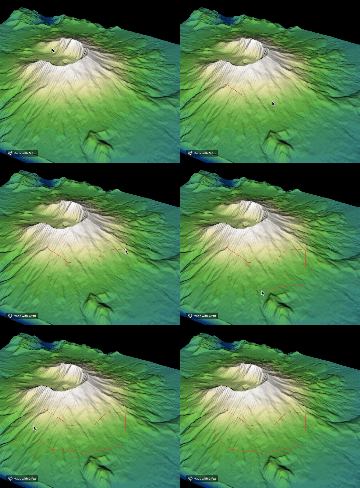
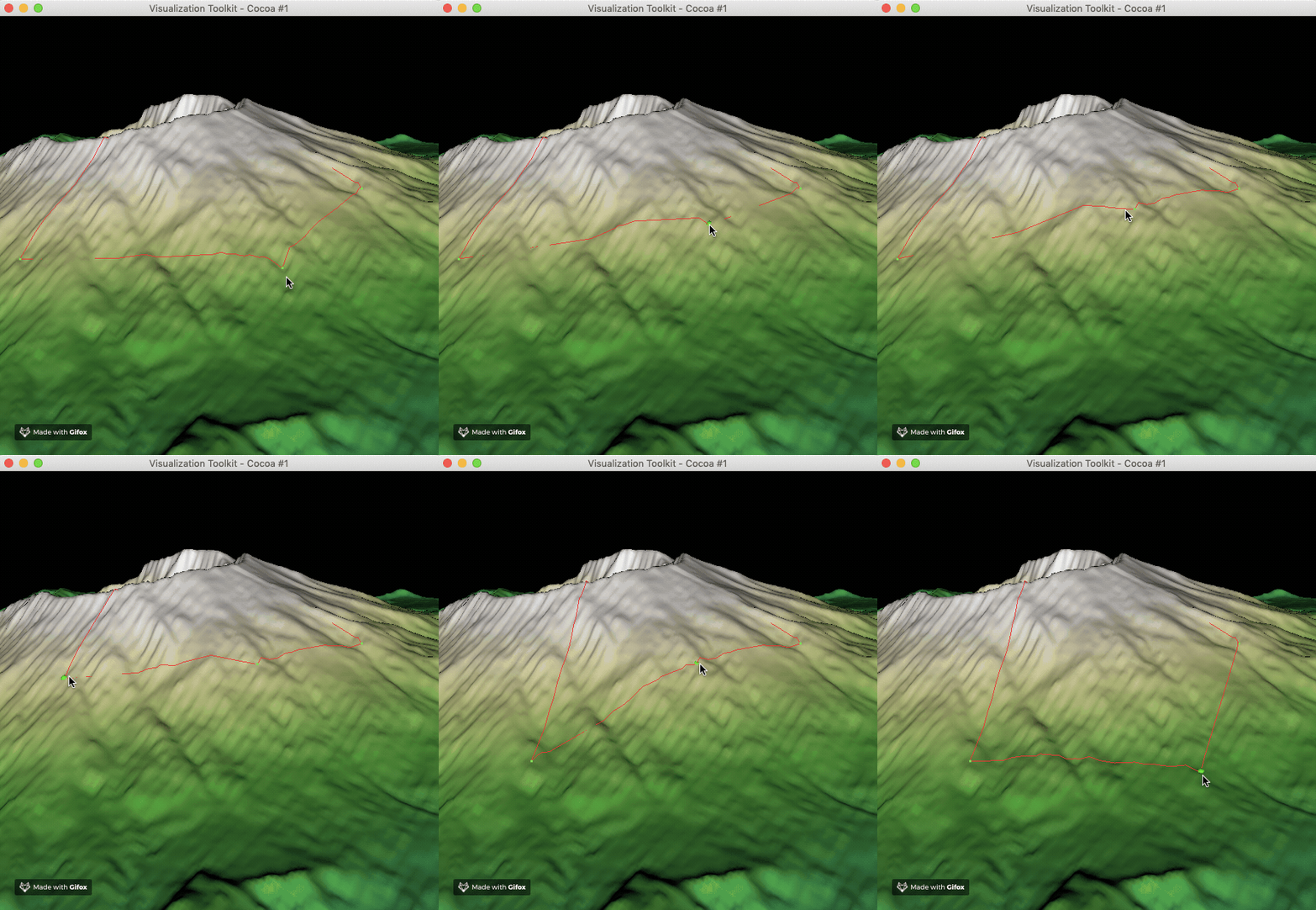
Extra code for display the complete model in the above content.
  vtkSmartPointer demActor =
    vtkSmartPointer::New();
  demActor->SetMapper(demMapper);

  // Create the RenderWindow, Renderer and the DEM + path actors.

  vtkSmartPointer ren1 =
    vtkSmartPointer::New();
  vtkSmartPointer renWin =
    vtkSmartPointer::New();
  renWin->AddRenderer(ren1);
  vtkSmartPointer iren =
    vtkSmartPointer::New();
  iren->SetRenderWindow(renWin);

  // Add the actors to the renderer, set the background and size

  renWin->SetSize(600,600);
  ren1->AddActor(demActor);
  ren1->ResetCamera();
  ren1->ResetCameraClippingRange();

  renWin->Render();
  iren->Initialize();
  iren->Start();
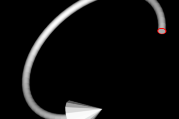
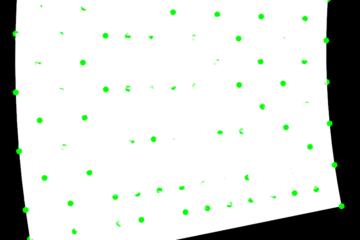
How to solve this missing line situation
The line is not missing, it’s just under mountain in the above image.
You can use “always on top” technology for your requirement.